SCHOOL OF ARCHITECTURE, COMPUTING & ENGINEERING
Submission instructions
- All pages to be numbered sequentially
| Module code | EG7004 | ||
| Module title | Soil Structure Engineering | ||
| Module leader | Dr Meghdad Bagheri | ||
| Assignment tutor | Dr John Walsh; Dr Meghdad Bagheri | ||
| Assignment title | Coursework Semester A 2025/26 | ||
| Assignment number | 1 | ||
| Weighting | 60% | ||
| Handout date | Monday 14th October 2024 | ||
| Submission date | Tuesday 16th December 2025 at 4.00 pm | ||
| Learning outcomes assessed by this assignment |
2, 4, 5, 6, 7 and 8 |
||
| Turnitin submission requirement | Yes | Turnitin GradeMark feedback used? | No |
| UEL Plus Grade Book submission used? | No | UEL Plus Grade Book feedback used? | No |
| Other electronic system used? | No | Are submissions / feedback totally electronic? | Yes |
| Additional information | None | ||
Form of Assessment:
1. Individual work
2. Group work
For group work assessment which requires members to submit both individual and group work aspects for the assignment, the work should be submitted as:
Consolidated single document Separately by each member
Number of assignment copies required:
1
2
Other
Assignment to be presented in the following format:
- On-line submission
- Stapled once in the top left-hand corner
- Glue bound
- Spiral bound
- Placed in a A4 ring bound folder (not lever arch)
Soft copy:
- CD (to be attached to the work in an envelope or purpose made wallet adhered to the rear)
- USB (to be attached to the work in an envelope or purpose made wallet adhered to the rear)
- Soft copy not required
Struggling With Your EG7004 Soil Structure Engineering Assignment 1?
EG7004 Coursework Semester A 2025–26
Your coursework will comprise the development and analysis of a preliminary design for a support system for a deep braced excavation in granular soil
The excavation is for a cut and cover tunnel for a sewerage pumping scheme, as indicated in Figure 1. The scheme involves the installation of a 3.2 metre internal diameter circular culvert as shown which is going to be installed using a cut and cover technique.
Ground investigation for the project has shown that the ground conditions comprise layers of SAND and GRAVEL of varying thickness extending to a depth of approximately 30 metres below existing ground level. The depth to groundwater typically varies between 20.0 and 25.0 metres.
Typical Ground conditions are shown in Figure 2.
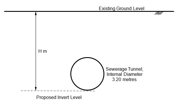
Figure 1 – Schematic View of Proposed Sewerage Tunnel
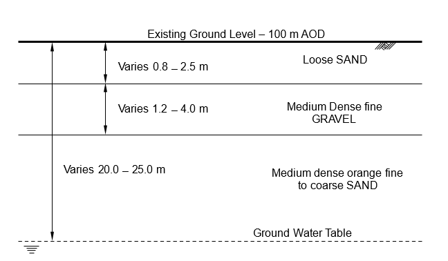
Figure 2 – Schematic View of Ground Conditions at the Site
Each student is to design a slightly different section of the excavation, taking into account the variation in thickness of each soil layer and in soil strength parameters at different locations
The first thing that you will need to do in order to complete this coursework is to log on to the Moodle site for this Module and obtain the values of the following for your specific design section:
- The required depth of excavation
- The thickness of each soil layer and its strength and stiffness parameters
- The depth to groundwater
These will be given in an Excel spreadsheet cross-referenced against your student number.
Note that for construction purposes the excavation will need to extend to a depth of 1.0 metre below the proposed tunnel invert level.
If you cannot find this information, then you MUST contact Dr Walsh IMMEDIATELY.
Coursework Submission – Design Report
Your coursework submission will comprise a summary preliminary design report and proposal for the support system for the excavation,
In developing your proposal two alternative design approaches are going to be considered:
- Design using the DPL Method as defined in CIRIA Report C517 (1999) Temporary propping of deep excavation – guidance on design.
- Design using Oasys FREW (2021) Software.
The DPL Method will be used to determine an initial design, and this design will then be analysed in detail using the FREW Software.
The design process may be iterative, with a first attempt made using the DPL Method which may then be revised depending on the results of the FREW analysis.
The excavation will be supported using AZ 32-750 Sheet piles to form the wall and props will comprise 273 mm diameter 10 mm wall thickness circular hollow section steel tubes.
Note:
Properties for the wall section may be obtained from the Arcelor Piling Handbook, which is downloadable from:
https://sheetpiling.arcelormittal.com/download–center/ and for the CHS section from:
https://www.tatasteelbluebook.com/en–gb/building–codes/eurocode–3/uk–
na/structural–hollow–sections
Your coursework submission will take the form of a design report, which will include the following sections:
a) A statement summarising the final design of the support system together with a construction drawing which provides sufficient information for a competent contractor to install the system as designed.
[Your construction drawing will be Submitted as a separate file from the main body of the report]
[20 Marks]
b) A summary description of the theoretical approach used to identify your initial DPL design and to develop this to produce your final design.
This will include appropriate discussion and references to any specific theories, references or design standards which have been used in the development of the design.
[Where detailed calculations have been carried out, these should be included in a separate Appendix with appropriate reference made to these in the text of the main report]
[10 Marks]
c) A summary of the Design Input Parameters.
This will include all of the parameters which have been used in the final design and should be presented in tabular form.
[Where parameters have been derived by calculation rather than being directly stated in the input data, the calculations to derive these should again be presented in a separate Appendix with appropriate reference to these made in the main text of the report]
[10 Marks]
d) A summary of the DPL analysis carried out.
This should include an explanation of the design decisions taken to determine the final prop levels and spacings and a summary of the predicted prop loads.
[Detailed calculations provided in a separate Appendix and referenced appropriately in the main body of the text]
[20 Marks]
e) A summary of the FREW analyses carried out to determine the required pile toe level and prop loads for the design developed using the DPL analysis assuming moderately conservative soil stiffness values.
This is to include consideration and explanation of the wall construction sequence adopted in the design.
[Detailed calculations and any computer output to be included in a separate Appendix, referenced appropriately in the main body of the text]
[20 Marks]
f) A reanalysis of the wall as carried out in section (e), but assuming a worst possible soil stiffness case.
[Detailed calculations/computer output in separate Appendix, referenced appropriately in the main body of the text]
[10 Marks]
g) A discussion of the findings of the analyses as carried out and reported in sections (d) to (f).
This should include an assessment of what the findings suggest about the suitability and efficiency of the final design, including a commentary on any variations in the various values obtained for each of the different analyses.
[10 Marks]
Notes on Coursework Submission:
As noted, your submission is to take the form of a design report
As such sections (b) to (g) should contain
- An explanation of all the assumptions that have been made in the design together with appropriate justification of these assumptions
- A summary of the key elements of the design, supported by drawings as necessary, sufficient that a Contractor could take the information provided and install the support system as designed
- A full summary of the expected performance of the support system, i.e. expected prop loads and any other relevant data obtained in the analyses e.g. maximum moments, expected wall deflections etc.
Given that the submission is to take the form of a design report, design calculations should not in general be included in the main text of the report but should be contained in Appendices to the report. References to the Appendices should then be made where appropriate in the main body of the report.
Where design calculations are presented as Appendices these should be brief, relevant and to the point. MARKS WILL BE DEDUCTED for reports which are “padded out” with unnecessary computer output or additional data related to calculations.
In preparing and submitting your coursework, please also note the following general guidance
- Final reports should be word processed in one and a half or double spaced Arial 12 point font.
- Where computer output is included, it is important that this is done in such a way that it is possible to check BOTH the INPUT to and OUTPUT values from the software.
Want a High-Quality Solution for Your EG7004 Coursework?
The post EG7004 Soil Structure Engineering Assignment 1 Coursework Semester A 2025/26 | University of East London (UOEL) appeared first on Students Assignment Help UK.